<Part 3> Make spinning 3D shapes in SDL2 and OpenGL
Let’s make it 3D (and spinning)!
Up to now, we've created a window in SDL2 using OpenGL, built a Mesh, and began writing shaders in GLSL to get a stretched-out square. In this final part, we will explain rendering in 3D, making things spin, and the Linear Algebra behind it!
DISCLAIMER: This walkthrough assumes knowledge from Part 1 and Part 2 and a working knowledge of C++ and how to compile it.
GitHub Repo: https://github.com/HadiCya/spinning_shapes
YouTube Version:
Getting Mathematical!
We're going to be running these calculations in our main.cpp file, and we'll get started by updating our includes:
#include <iostream>
#include <SDL.h>
#include "mesh.h"
#include "loadShader.h"

#include <glm/glm.hpp>
#include <glm/gtc/matrix_transform.hpp>
#include <glm/gtc/type_ptr.hpp>
Here, we will include the necessary headers for linear algebra operations using the GLM library. This enables the main application to work with vectors and matrices required for 3D transformations.
We're going to now create and configure matrices for transforming the object in 3D space. We're going to write this code after we call glClear() in our while loop.
Model Matrix
glm::mat4 model = glm::mat4(1.0f);
model = glm::rotate(model, glm::radians(50.0f), glm::vec3(0.5f, 1.0f, 0.0f));
This line of code creates a rotation matrix. In computer graphics, rotation matrices are used to rotate objects around a specified axis.
Let's get into the math behind the code:
Initially, we define model as an Identity matrix, which, in linear algebra, is practically 1.
$$model = \begin{bmatrix} 1 & 0 & 0 & 0 \\ 0 & 1 & 0 & 0 \\ 0 & 0 & 1 & 0 \\ 0 & 0 & 0 & 1 \end{bmatrix}$$
glm::vec3(0.5f, 1.0f, 0.0f) defines the axis of rotation. Here, it's a vector pointing partially up and partially towards the x-axis:
$$\vec{u} = \left<0.5, 1, 0 \right>$$
We need to normalize the axis:
$$\vec{u'} = \left< \frac{0.5}{\sqrt{0.5^2 + 1^2}}, \frac{1}{\sqrt{0.5^2 + 1^2}}, 0 \right>$$
glm::radians(50.0f) converts 50 degrees into radians, as trigonometric functions in GLM use radians:
$$\theta = \text{radians}(50) = \frac{50 \pi}{180}$$
The glm::rotate function creates a 4x4 matrix that rotates points in 3D space around the given axis by the specified angle. The rotation matrix is derived from Rodrigues' rotation formula, combining the components of the axis vector and the sine and cosine of the angle.
$$R = \begin{bmatrix} \cos(\theta) + u_x^2 (1 - \cos(\theta)) & u_xu_y(1 - \cos(\theta)) - u_z\sin(\theta) & u_xu_z(1 - \cos(\theta)) + u_y\sin(\theta) & 0 \\ u_yu_x(1 - \cos(\theta)) + u_z\sin(\theta) & \cos(\theta) + u_y^2(1 - \cos(\theta)) & u_yu_z(1 - \cos(\theta)) - u_x\sin(\theta) & 0 \\ u_zu_x(1 - \cos(\theta)) - u_y\sin(\theta) & u_zu_y(1 - \cos(\theta)) + u_x\sin(\theta) & \cos(\theta) + u_z^2(1 - \cos(\theta)) & 0 \\ 0 & 0 & 0 & 1 \end{bmatrix}$$
When you plug in everything we've calculated thus far into Matrix R, the resulting matrix will be stored into model.
View Matrix
glm::mat4 view = glm::mat4(1.0f);
view = glm::translate(view, glm::vec3(0.0f, 0.0f, -3.0f));
The view matrix is used to transform vertices from world space to camera (view) space. It's analogous to moving and orienting a camera within the scene.
glm::vec3(0.0f, 0.0f, -3.0f) indicates that the view is being translated along the z-axis.
$$\vec{t} = \left<0, 0, -3 \right>$$
The glm::translate function constructs a 4x4 translation matrix. This matrix is an identity matrix with the translation vector added to the fourth column. It shifts the position of all points in the scene relative to the camera.
For a translation by a vector t, the translation matrix T is:
$$T = \begin{bmatrix} 1 & 0 & 0 & t_x \\ 0 & 1 & 0 & t_y \\ 0 & 0 & 1 & t_z \\ 0 & 0 & 0 & 1 \end{bmatrix}$$
When you plug in vector t into Matrix T, the resulting matrix will be stored into view.
Projection Matrix
glm::mat4 projection = glm::perspective(glm::radians(60.0f), float(screen_width)/(float)screen_height, 0.1f, 100.0f);
The projection matrix maps a 3D world into a 2D view, akin to how a camera lens focuses light onto a film.
glm::perspective creates a frustum that defines the visible space. It scales the x and y coordinates of vertices based on their depth (z-value), causing more distant objects to appear smaller and creating a sense of depth.
The frustum in the context of the glm::perspective function is a crucial concept in 3D graphics, especially concerning the perspective projection matrix. Let's break down what a frustum is and how it works in the creation of a perspective projection:
What is a Frustum?
A frustum in 3D graphics is a geometric shape that resembles a pyramid with the top cut off. In the case of perspective projection, it's more specifically a truncated pyramid.
The frustum defines the portion of the 3D space that is visible through the camera. Only objects within this frustum will be rendered on the screen.
Components of the Frustum:
Near Plane: This is the closest plane to the viewer (camera). In your code, it's set to 0.1f units from the viewer. Objects closer than this plane are not visible or rendered.
$$z_{near} = 0.1$$
Far Plane: This is the farthest plane from the viewer, set to 100.0f units in your code. Objects beyond this distance are also not visible or rendered.
$$z_{far} = 100.0$$
Sides of the Frustum: The sides of the frustum are defined by the field of view (FOV). A wider FOV creates a wider frustum, capturing a broader view of the scene but potentially introducing more distortion (similar to a wide-angle lens in photography).
glm::radians(60.0f)specifies the vertical FOV in radians. A wider FOV can capture more of the scene but can also introduce more distortion.$$fov_y = \text{radians}(60) = \frac{60 \pi}{180}$$
Top and Bottom: The aspect ratio (width divided by height) determines the relative heights of the top and bottom planes of the frustum.
$$aspect = \frac{\text{screen width}}{\text{screen height}}$$
Role in Perspective Projection:
The purpose of the frustum in perspective projection is to define how 3D coordinates are projected onto the 2D plane of the screen.
The projection matrix, P, maps coordinates from this 3D frustum to a normalized 2D coordinate system. It scales the x and y coordinates of the vertices based on their z-value (depth), which makes objects appear smaller as they get farther away, creating a realistic depth perception.
$$P = \begin{bmatrix} \frac{\cot{(\frac{fov_y}{2})}}{aspect} & 0 & 0 & 0 \\ 0 & \cot{(\frac{fov_y}{2})} & 0 & 0 \\ 0 & 0 & \frac{z_{\text{far}} + z_{\text{near}}}{z_{\text{near}} - z_{\text{far}}} & \frac{2 \times z_{\text{far}} \times z_{\text{near}}}{z_{\text{near}} - z_{\text{far}}} \\ 0 & 0 & -1 & 0 \end{bmatrix}$$
When you plug in everything we've calculated thus far into Matrix P, the resulting matrix will be stored into projection.
Connecting it to the vertex shader
Now, we need a way to pass these matrices into the vertex shader.
        int modelLoc = glGetUniformLocation(programID, "model");
        glUniformMatrix4fv(modelLoc, 1, GL_FALSE, glm::value_ptr(model));

        int viewLoc = glGetUniformLocation(programID, "view");
        glUniformMatrix4fv(viewLoc, 1, GL_FALSE, glm::value_ptr(view));

        int projectionLoc = glGetUniformLocation(programID, "projection");
        glUniformMatrix4fv(projectionLoc, 1, GL_FALSE, glm::value_ptr(projection));
We are going to pass the model, view, and projection matrices to the shaders. The glUniformMatrix4fv function is an OpenGL function that sets the value of a uniform matrix variable in the shaders. It takes the location of the uniform variable, the number of matrices (1 in this case), a flag for matrix transpose (set to GL_FALSE), and a pointer to the data.
In vertex.glsl, we're going to need to grab the variables that we've just defined:
#version 330 core

layout (location = 0) in vec3 aPos;
uniform mat4 model;
uniform mat4 view;
uniform mat4 projection;

void main() {
    gl_Position = projection * view * model * vec4(aPos, 1.0);
}
When combining these matrices, the order of multiplication is crucial. The typical order in OpenGL for transforming a vertex v is:
Model transformation (rotation in this case)
View transformation (translation)
Projection transformation
So, the combined transformation matrix M is given by:
$$M = P \times T \times R$$
The final transformed vertex v is obtained by multiplying the vertex's homogeneous coordinate vector v with M:
$$v' = M \times v$$
This process transforms the vertex from its local space (model transformation) to world space (view transformation), and finally to normalized device coordinates (projection transformation), ready for rasterization and rendering on the screen.
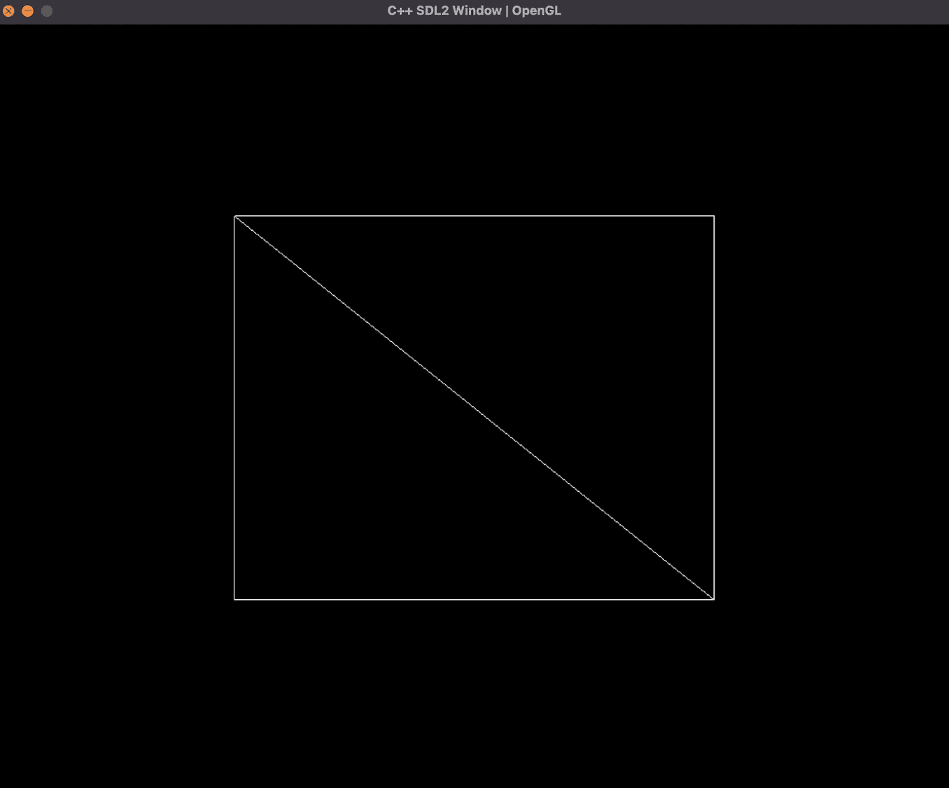
Before we do that, we're going to need to update our vertices and triangle arrays in mesh.cpp to be a 3D cube:
    GLfloat vertices[] = {
        0.5f, -0.5f, 0.5f,
        -0.5f, -0.5f, 0.5f,
        0.5f, 0.5f, 0.5f,
        -0.5f, 0.5f, 0.5f,
        0.5f, -0.5f, -0.5f,
        -0.5f, -0.5f, -0.5f,
        0.5f, 0.5f, -0.5f,
        -0.5f, 0.5f, -0.5f
    };
    GLint triangles[] = {0, 2, 3, 0, 3, 1,
                          2, 6, 7, 2, 7, 3,
                          6, 4, 5, 6, 5, 7,
                          4, 0, 1, 4, 1, 5,
                          1, 3, 7, 1, 7, 5,
                          4, 6, 2, 4, 2, 0};
If you forgot how we did this last time, look at Part 2 for a more detailed explanation.
Let's go ahead and run this code! This is what my compilation command looks like now:
clang++ -std=c++20 main.cpp mesh.cpp loadShader.cpp ./glad/src/glad.c -o spinning_shapes -I/Library/Frameworks/SDL2.framework/Headers -I./glad/include -I./glm/ -F/Library/Frameworks -framework SDL2
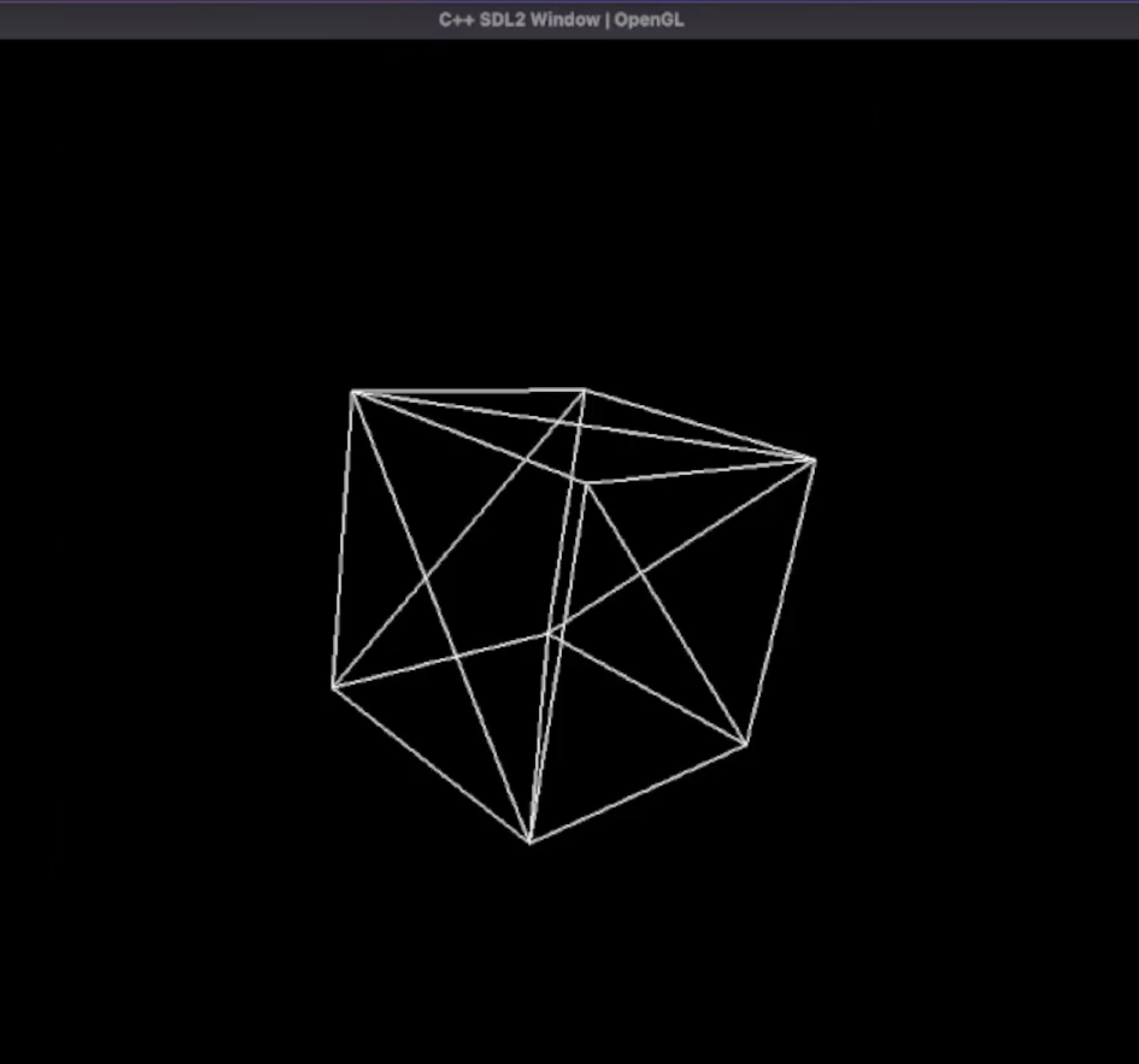
If you see a 3D cube, congrats! We are close to making it spin.
Making it spin!
To make it spin, all we're going to need to do is update our model matrix to rotate with time instead of staying at 50 degrees.
In main.cpp update the code to:
Add Uint32 lastUpdate = SDL_GetTicks(); under the declaration of done
Add Uint32 current = SDL_GetTicks(); as soon as the while loop begins
Add float dT = (current — lastUpdate) / 1000.0f; underneath the glClear() call
Add *dT to the rotate matrix in the model declaration so that it looks like:
model = glm::rotate(model, glm::radians(50.0f)*dT, glm::vec3(0.5f, 1.0f, 0.0f));
Simply, this code is going to calculate the difference in time between frames, and then multiply that difference by our rotation, so that it consistently rotates each frame.
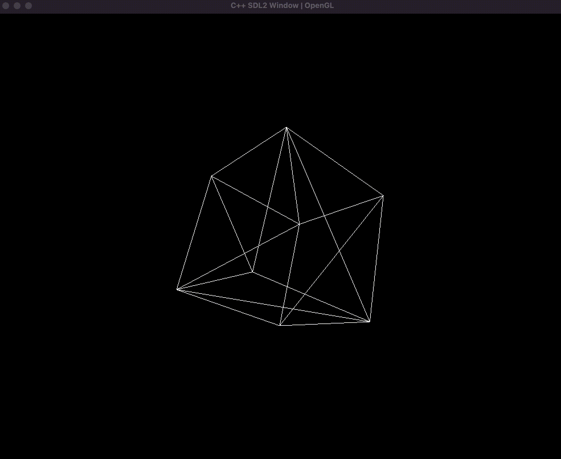
Spinning cube. Speaks for itself.
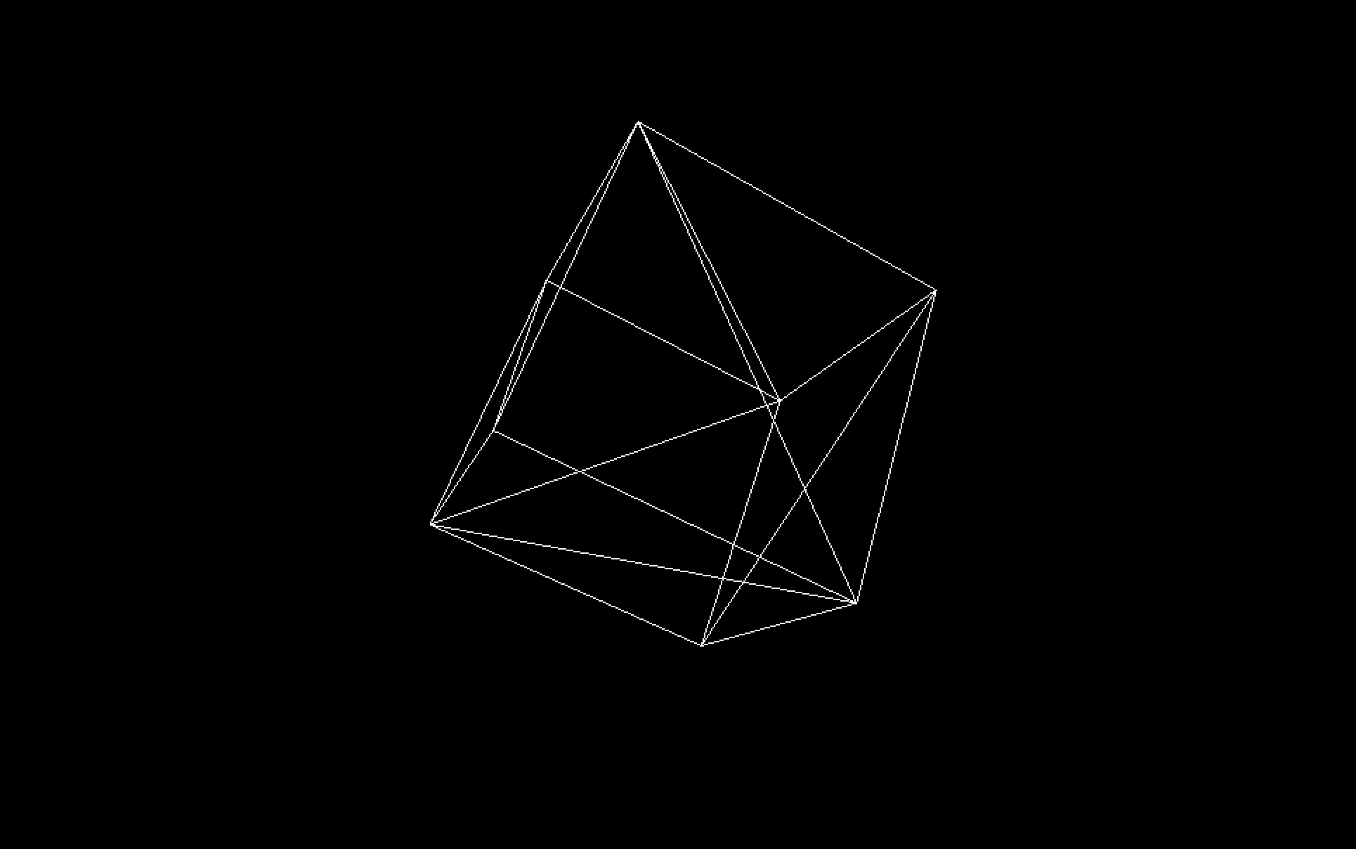
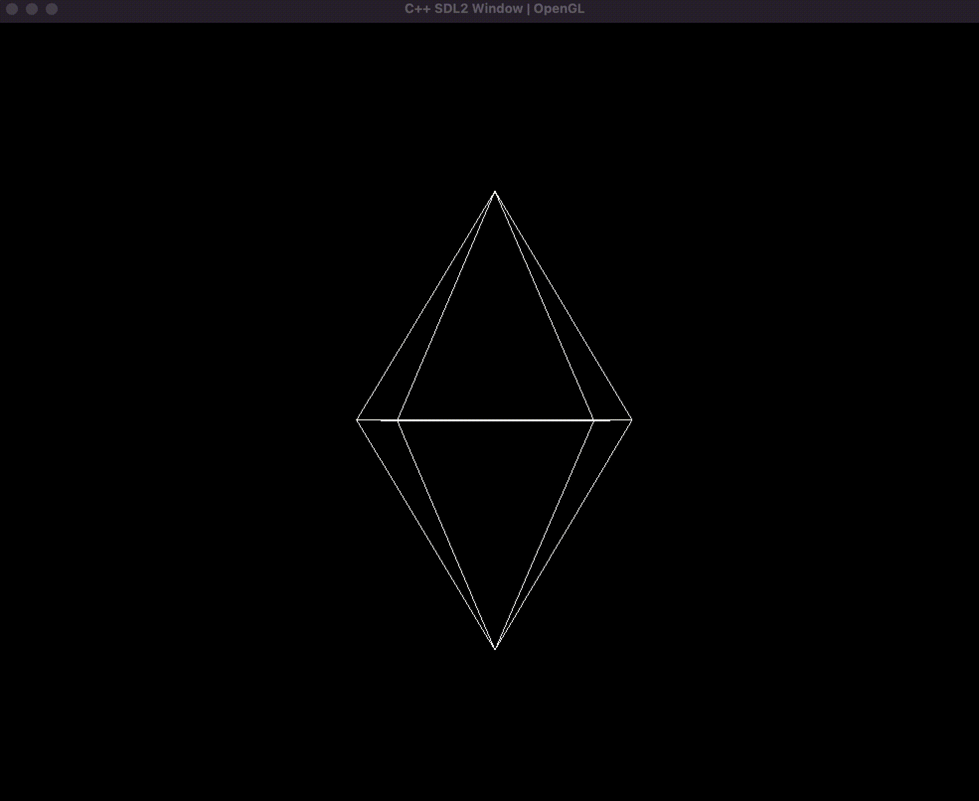
BONUS: Spinning Rhombus
In mesh.cpp update the vertices and triangles to make a rhombus:
    GLfloat vertices[] = {
        0.5f, 0.0f, 0.5f,
        -0.5f, 0.0f, 0.5f,
        -0.5f, 0.0f, -0.5f,
        0.5f, 0.0f, -0.5f,
        0.0f, 1.0f, 0.0f,
        0.0f, -1.0f, 0.0f
    };

    GLint triangles[] = {
        0, 4, 1,
        1, 4, 2,
        2, 4, 3,
        3, 4, 0,
        0, 5, 1,
        1, 5, 2,
        2, 5, 3,
        3, 5, 0};
Now when we run our code we get a Rhombus:
I suggest trying to make your mesh to get a better understanding of 3D spaces and how memory management works.
Wrapping Up
Throughout this series, we have embarked on an exciting journey into the world of 3D graphics programming. Starting from the basics of OpenGL and SDL initialization, we have explored fundamental concepts such as vertices, triangle arrays, and buffer management. Along the way, we’ve delved into the mathematical principles that make 3D rendering possible.
Key Takeaways
Understanding Vertices and Buffers: We understood the role that defining vertices and the order in which to draw them, and how buffers enable efficient storage and manipulation of these vertices on the GPU.
3D Transformations and Projection: Through matrix mathematics, we’ve seen how to translate, rotate, and scale objects in a 3D space. While OpenGL GLM handles this math for us, we took the opportunity to see what was happening behind the scenes. We also learned how perspective projection brings depth to our rendering.
Creating our Spinning Cube! By combining all of the elements we learned, we were able to render a spinning 3D cube, which is the first building block for creating far more complex 3D scenes.
What’s Next?
The door to 3D graphics programming is now wide open. With the foundation laid in this series, you can explore further topics such as:
Texture Mapping: Adding textures to give surfaces realistic appearances.
Lighting and Shading: Implementing various lighting models to create a more lifelike scene.
3D Modeling and Animation: Importing and manipulating complex 3D models, and creating intricate animations.
Whether you’re looking to build a game, create a simulation, make a movie, or simply experiment with 3D graphics, the skills you’ve acquired here will be a valuable asset.
Thank you for joining me on this adventure into 3D graphics programming. Keep experimenting, learning, and most importantly, having fun! Build your castle in the skies, your creativity and intellect will be enough :)
Happy coding!